|
|
Post by John on Dec 5, 2008 11:41:24 GMT -5
Another one for Trev, were there three winders at Cotgrave Trev?? Two in the upcast shaft and one for men and materials in the downcast?
Were they on the Ward-Leonard system or resistances on a slipring motor?
I have some notes on faultfinding on the winders somewhere.
|
|
|
|
Post by garryo on Mar 17, 2009 8:50:27 GMT -5
Cot grave Winders
John
Cotgrave as you stated had three winders named 1A & 1B in one tower and No2 in the other tower, all three were 4 rope friction winders originally designed by BTH later AEI.
The control was AC drive motors of 1800HP with rotor resistance fitted with dynamic braking.
No1A and 1b operated to a depth of 1940ft and each system had a skip and counterweight.
No2 had a cage and counterweight and wound to about 1800ft
John I think this info is correct from my data base which contains nearly all the friction winders installed in the UK from the first modern one at Snowdon to Maltby No3 and Asfordby
|
|
|
|
Post by John on Mar 17, 2009 9:24:47 GMT -5
I thought my memory wasn't fading that much Garry, would have been tow for skip winding and one in tother shaft for men and materials.
Although I never worked on them, my time there was always underground, I do have the fault finding paperwork on the winders somewhere among my papers.
I do recall when we were taken on a visit to Cotgrave after we were told Clifton was closing, being shown the winders, impressive at that time seeing koepe winders after many years of seeing two steam winders!
|
|
|
|
Post by John on May 5, 2013 11:14:31 GMT -5
First face's at Cotgrave were in the Deep Soft seam on the south side, 53's was the first in production, then 3's, 2's, 5's and 4's.
Deep soft was abandoned due to heavy floorlift problems.
All mining then was carried out in the Deep hard seam for many years.
During my time there, the Elec Chargehand on the shift I was on was Dennelly Pickering.
Brian Old was the assistant Elec Chargehand.
No2 shaft during my short time there had two double deck cages.....I remember this because of a short lived dispute we had when they decided to single deck near the end of a dayshift winding time, there was time enough to wind all of the electrical staff and half the fitters who would have been on the last draw down... I was one of those... They were going to dock us all half an hours pay for "late riding" which they, the management had caused.... It was only resolved when we started to walk back to the showers, amazing how quickly when they realized they had screwed up big time and would have had no elecs or fitters underground for that shift...Plus it may well have escalated into a longer walkout......
Jeeze we were "Bolshy" back then..
|
|
|
|
Post by rpriv2000 on Aug 16, 2014 4:36:31 GMT -5
Another one for Trev, were there three winders at Cotgrave Trev?? Two in the upcast shaft and one for men and materials in the downcast? Were they on the Ward-Leonard system or resistances on a slipring motor? I have some notes on faultfinding on the winders somewhere. Could anyone point me in the right direction for the original design dimensions for the koepe towers at Cotgrave, please? There are numerous pictures but I am not able to find actual measurements. |
|
|
|
Post by John on Aug 16, 2014 6:17:42 GMT -5
Another one for Trev, were there three winders at Cotgrave Trev?? Two in the upcast shaft and one for men and materials in the downcast? Were they on the Ward-Leonard system or resistances on a slipring motor? I have some notes on faultfinding on the winders somewhere. Could anyone point me in the right direction for the original design dimensions for the koepe towers at Cotgrave, please? There are numerous pictures but I am not able to find actual measurements. |
|
|
|
Post by smshogun on Aug 26, 2014 21:26:31 GMT -5
They were 128' high and portal framed structures (steel girder framed) with cast concrete around the portal frame, this allowed them to be cast floor by floor and have all fixings installed to the portal frame prior to pouring the concrete.
They were encased in steel sheeting onto a secondary steel framing attached to the portal framing which was not structural, and as a qualified abseiler I used to examine them periodically.
Roofs were also cast concrete with an access hatch in the centre, this also had the anchor point for harnesses to be attached, the roof was originally bitumen covered which was later replaced with a poly-alkyd bitumen which was a form of synthetic bitumen with none of the traditional tars added to it.
Both towers had lighting fitted to the roof and I designed and built the last systems which were telescopic so they could be retracted for maintenance and also hinged so once retracted they could be flipped over so electricians weren't working near the edge of the roof to prevent tools and sodium tubes from being dropped off the edge of the towers. |
|
|
|
Post by rpriv2000 on Aug 27, 2014 15:21:05 GMT -5
Thank you for that. I assume that was for the smaller tower? I don't suppose you have the floor dimensions and overhang? And distance between the towers.... though we should be able to glean that from floor plans available at CA Mansfield.
I am a member of the steering group for the Cotgrave Colliery Memorial Group. We plan, with partners, to produce a lasting memorial for the mine and its workers in the country park near to the original pit head which is in the process of being redeveloped for housing. The present intention is for a permanent and imposing memorial structure, an heritage trail with information stations along with an associated website with history of the colliery. The project is important for Cotgrave as the mine was entirely responsible for a tenfold increase in its population and a lasting mining heritage. We would like to gather as much accurate information about the entire operational history of the mine to make available through the memorial, trail and website.
One of the items we would like to produce is a model of the towers. Clearly they are so iconic that any fluctuation in scale would show and be bound to be picked up by Cotgrave Ex Miners so its important we get it right! Also its early days but if you, or anyone else here, would like to be involved in this project please let me know. Thanks, again.
|
|
|
|
Post by smshogun on Sept 13, 2014 20:18:35 GMT -5
According to my information they were the same height, just set on slightly different levels.
Overhangs were 90 feet from the bottom to floor level so must have been 38' high which sounds about correct, they would have needed such a height to get large items up to the top of the towers.
According to my unscaled drawings which I have tried to scale they would appear to be 40' square, but this is not accurate.
Below ground level there was 50' of foundations which was structurally integral to the top of the shaft, but they changed the ground levels some time during operations. |
|
|
|
Post by John on Jan 16, 2017 11:43:39 GMT -5
Back to winders, I'm picking up information that states the downcast shaft was installed with two independent winders, if so, when was it changed over to one single winder and why??
|
|
|
|
Post by eleceng on Jan 25, 2017 7:27:02 GMT -5
Before my time, John but there was no structure on the winder floor, or any other floors to indicate another engine had previously been installed.
|
|
|
|
Post by John on Jan 25, 2017 9:23:42 GMT -5
Before my time, John but there was no structure on the winder floor, or any other floors to indicate another engine had previously been installed.
I've come across other oddities in so called recorded colliery histories. One I found was Wollaton Colliery having three shafts! It's verified by the borehole/sinkers logs too, I can't find anything as to what happened to that third shaft. All the contemporary right ups say it had two shafts, nobody mentions the third shaft and whether it was sunk to coal, filled or what. I thought at first it was Radford, but no, again borehole/shaft sinking records show three shafts. Probably now, I'll never find out what happened. |
|
|
|
Winders.
Jan 26, 2017 16:08:27 GMT -5
via mobile
Post by Wheldale on Jan 26, 2017 16:08:27 GMT -5
John, just a thought about the third shaft...... I've seen some pits classed as having a third shaft as they had a large well for water. I wonder if This could be the case here?
|
|
|
|
Post by John on Jan 27, 2017 6:28:06 GMT -5
John, just a thought about the third shaft...... I've seen some pits classed as having a third shaft as they had a large well for water. I wonder if This could be the case here? |
|
|
|
Post by Wheldale on Jan 28, 2017 16:25:06 GMT -5
|
|
|
|
Post by John on Jan 28, 2017 17:40:13 GMT -5
|
|
|
|
Post by John on Jan 28, 2017 17:43:17 GMT -5
I did a quick search just now, is this the photo you tried to link?  It sure looks like a head frame, and you can see No2 and No3 shafts a bit further in the photo. So it looks like it did have three shafts at one time. 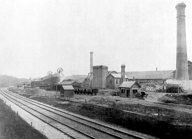 |
|
|
|
Post by John on Jan 28, 2017 17:50:14 GMT -5
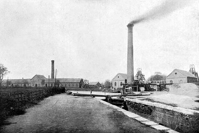
Here's another one and you can see a small sheave wheel mounted on the top.
|
|
|
|
Winders.
Jan 29, 2017 3:43:31 GMT -5
via mobile
Post by Wheldale on Jan 29, 2017 3:43:31 GMT -5
I did a quick search just now, is this the photo you tried to link? It sure looks like a head frame, and you can see No2 and No3 shafts a bit further in the photo. So it looks like it did have three shafts at one time. Yes, that's the one I tried to link. There another picture from a different angle, it shows a fan house next to the wooden stucture so it could possible be a ventilation shaft. |
|
|
|
Winders.
Jan 29, 2017 3:47:18 GMT -5
via mobile
Post by Wheldale on Jan 29, 2017 3:47:18 GMT -5
|
|
|
|
Post by John on Jan 29, 2017 6:27:30 GMT -5
That is the fan house, steam driven, you can see the top of the fan casing and as you say, probably the upcast shaft. I wonder when the shaft was filled and capped? There is a new photo of Wollaton which shows a more modern fan house and the head frame is missing, probably taken NCB era.
|
|
|
|
Post by John on Jan 29, 2017 10:53:27 GMT -5
Eureka!!!...Found some new info that's only been on the net under a year, the third shaft confirmed, 12 ft diameter, U/C and 500 yards deep. I haven't found out yet when it was filled and capped. I'll put the info about winders, etc on the Wollaton page later.
|
|
|
|
Post by paultay22 on Aug 19, 2018 12:45:47 GMT -5
Another one for Trev, were there three winders at Cotgrave Trev?? Two in the upcast shaft and one for men and materials in the downcast? Were they on the Ward-Leonard system or resistances on a slipring motor? I have some notes on faultfinding on the winders somewhere. |
|


 It sure looks like a head frame, and you can see No2 and No3 shafts a bit further in the photo. So it looks like it did have three shafts at one time.